顶点输入数据处理
本章概述了规范中的固定功能顶点处理章节,以帮助从高层次理解应用程序在使用图形管线时如何将数据映射到顶点着色器。
同样重要的是要记住,Vulkan 是一种可以以不同方式使用的工具。以下示例是为了教育目的,说明顶点数据可以如何布局。
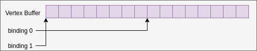
绑定和位置
binding 与顶点缓冲区中的一个位置相关联,顶点着色器在 vkCmdDraw* 调用期间将从此位置开始读取数据。更改 bindings 不需要对应用程序的顶点着色器源代码进行任何修改。
例如,以下代码与 bindings 的工作原理图匹配。
// Using the same buffer for both bindings in this example
VkBuffer buffers[] = { vertex_buffer, vertex_buffer };
VkDeviceSize offsets[] = { 8, 0 };

vkCmdBindVertexBuffers(
                        my_command_buffer, // commandBuffer
                        0,                 // firstBinding
                        2,                 // bindingCount
                        buffers,           // pBuffers
                        offsets,           // pOffsets
                      );
以下示例展示了根据您的数据输入设置 binding 和 location 值的各种方式。
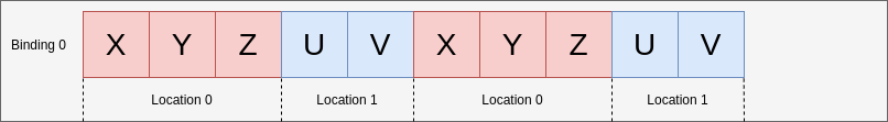
示例 A - 打包数据
对于第一个示例,每个顶点的属性数据将如下所示
struct Vertex {
    float   x, y, z;
    uint8_t u, v;
};
管线创建信息代码大致如下所示
const VkVertexInputBindingDescription binding = {
    0,                          // binding
    sizeof(Vertex),             // stride
    VK_VERTEX_INPUT_RATE_VERTEX // inputRate
};

const VkVertexInputAttributeDescription attributes[] = {
    {
        0,                          // location
        binding.binding,            // binding
        VK_FORMAT_R32G32B32_SFLOAT, // format
        0                           // offset
    },
    {
        1,                          // location
        binding.binding,            // binding
        VK_FORMAT_R8G8_UNORM,       // format
        3 * sizeof(float)           // offset
    }
};

const VkPipelineVertexInputStateCreateInfo info = {
    1,             // vertexBindingDescriptionCount
    &binding,      // pVertexBindingDescriptions
    2,             // vertexAttributeDescriptionCount
    &attributes[0] // pVertexAttributeDescriptions
};
将使用此 GLSL 代码如下所示
layout(location = 0) in vec3 inPos;
layout(location = 1) in uvec2 inUV;
示例 B - 填充和调整偏移量
此示例检查顶点数据未紧密打包且具有额外填充的情况。
struct Vertex {
    float   x, y, z, pad;
    uint8_t u, v;
};
唯一需要的更改是在管线创建时调整偏移量
        1,                          // location
        binding.binding,            // binding
        VK_FORMAT_R8G8_UNORM,       // format
-        3 * sizeof(float)           // offset
+        4 * sizeof(float)           // offset
因为现在将为 u 和 v 从哪里读取设置正确的偏移量。

示例 C - 非交错
有时数据不是交错的,在这种情况下,您可能会有以下情况
float position_data[] = { /*....*/ };
uint8_t uv_data[] = { /*....*/ };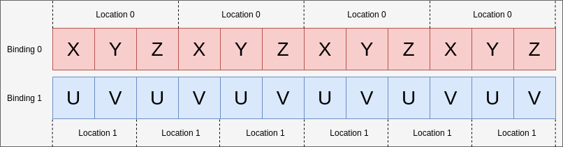
在这种情况下,将有 2 个绑定,但仍然有 2 个位置
const VkVertexInputBindingDescription bindings[] = {
    {
        0,                          // binding
        3 * sizeof(float),          // stride
        VK_VERTEX_INPUT_RATE_VERTEX // inputRate
    },
    {
        1,                          // binding
        2 * sizeof(uint8_t),        // stride
        VK_VERTEX_INPUT_RATE_VERTEX // inputRate
    }
};

const VkVertexInputAttributeDescription attributes[] = {
    {
        0,                          // location
        bindings[0].binding,        // binding
        VK_FORMAT_R32G32B32_SFLOAT, // format
        0                           // offset
    },
    {
        1,                          // location
        bindings[1].binding,        // binding
        VK_FORMAT_R8G8_UNORM,       // format
        0                           // offset
    }
};

const VkPipelineVertexInputStateCreateInfo info = {
    2,             // vertexBindingDescriptionCount
    &bindings[0],  // pVertexBindingDescriptions
    2,             // vertexAttributeDescriptionCount
    &attributes[0] // pVertexAttributeDescriptions
};
GLSL 代码与示例 A 没有变化
layout(location = 0) in vec3 inPos;
layout(location = 1) in uvec2 inUV;
示例 D - 2 个绑定和 3 个位置
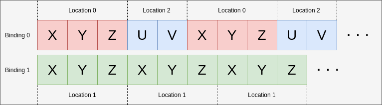
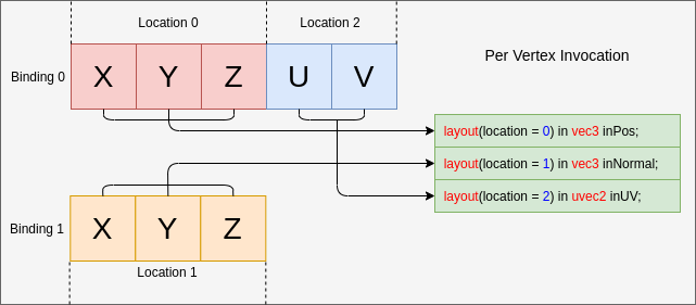
此示例旨在帮助说明 binding 和 location 是相互独立的。
在此示例中,顶点的布局数据以两种缓冲区格式提供,格式如下
struct typeA {
    float   x, y, z; // position
    uint8_t u, v;    // UV
};

struct typeB {
    float x, y, z; // normal
};

typeA a[] = { /*....*/ };
typeB b[] = { /*....*/ };
并且正在使用的着色器的接口如下
layout(location = 0) in vec3 inPos;
layout(location = 1) in vec3 inNormal;
layout(location = 2) in uvec2 inUV;
仍然可以通过相应地设置 VkVertexInputBindingDescription 和 VkVertexInputAttributeDescription 来正确映射
const VkVertexInputBindingDescription bindings[] = {
    {
        0,                          // binding
        sizeof(typeA),              // stride
        VK_VERTEX_INPUT_RATE_VERTEX // inputRate
    },
    {
        1,                          // binding
        sizeof(typeB),              // stride
        VK_VERTEX_INPUT_RATE_VERTEX // inputRate
    }
};

const VkVertexInputAttributeDescription attributes[] = {
    {
        0,                          // location
        bindings[0].binding,        // binding
        VK_FORMAT_R32G32B32_SFLOAT, // format
        0                           // offset
    },
    {
        1,                          // location
        bindings[1].binding,        // binding
        VK_FORMAT_R32G32B32_SFLOAT, // format
        0                           // offset
    },
    {
        2,                          // location
        bindings[0].binding,        // binding
        VK_FORMAT_R8G8_UNORM,       // format
        3 * sizeof(float)           // offset
    }
};
示例 E - 理解输入属性格式
VkVertexInputAttributeDescription::format 可能会引起混淆。 format 字段只是描述着色器应读取的数据的大小和类型。
使用 VkFormat 值的原因是它们定义明确,并且与顶点着色器的输入布局匹配。
对于此示例,顶点数据只是四个浮点数
struct Vertex {
    float a, b, c, d;
};
读取的数据将与 format 和 offset 的设置方式重叠
const VkVertexInputBindingDescription binding = {
    0,                          // binding
    sizeof(Vertex),             // stride
    VK_VERTEX_INPUT_RATE_VERTEX // inputRate
};

const VkVertexInputAttributeDescription attributes[] = {
    {
        0,                          // location
        binding.binding,            // binding
        VK_FORMAT_R32G32_SFLOAT,    // format - Reads in two 32-bit signed floats ('a' and 'b')
        0                           // offset
    },
    {
        1,                          // location
        binding.binding,            // binding
        VK_FORMAT_R32G32B32_SFLOAT, // format - Reads in three 32-bit signed floats ('b', 'c', and 'd')
        1 * sizeof(float)           // offset
    }
};
当在着色器中读取数据时,重叠位置的值将相同
layout(location = 0) in vec2 in0;
layout(location = 1) in vec2 in1;

// in0.y == in1.x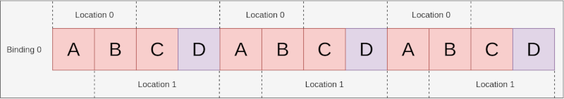
重要的是要注意到 in1 是一个 vec2,而输入属性是 VK_FORMAT_R32G32B32_SFLOAT,这并不完全匹配。根据规范
如果顶点着色器的组件较少,则会丢弃多余的组件。
因此,在这种情况下,位置 1 (d) 的最后一个组件将被丢弃,着色器不会读取它。
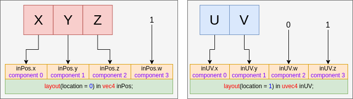
组件分配
规范更详细地解释了Component分配。 以下是该主题的总体概述。
填充组件
VkVertexInputAttributeDescription 中的每个 location 都有 4 个组件。 上面的示例已经表明,当着色器输入具有较少的组件时,将丢弃来自 format 的额外组件。
VK_FORMAT_R32G32B32_SFLOAT有 3 个组件,而vec2只有 2 个
对于相反的情况,规范 有一个表格显示它将如何扩展缺失的组件。
这意味着以下示例
layout(location = 0) in vec3 inPos;
layout(location = 1) in uvec2 inUV;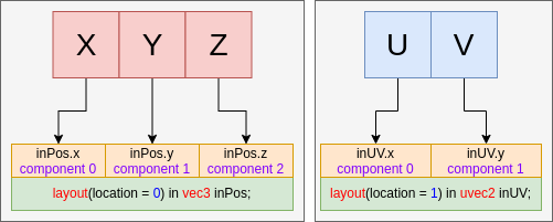
将以上述方式填充示例
layout(location = 0) in vec4 inPos;
layout(location = 1) in uvec4 inUV;