组合图像采样器
简介
在教程的统一缓冲区部分,我们第一次了解了描述符。在本章中,我们将介绍一种新的描述符类型:组合图像采样器。此描述符使着色器可以通过类似于我们在上一章中创建的采样器对象来访问图像资源。
我们将首先修改描述符集布局、描述符池和描述符集,以包含这样的组合图像采样器描述符。之后,我们将向 `Vertex` 添加纹理坐标,并修改片段着色器以从纹理读取颜色,而不是仅仅插值顶点颜色。
更新描述符
浏览到 `createDescriptorSetLayout` 函数,并为组合图像采样器描述符添加一个 `VkDescriptorSetLayoutBinding`。我们只需将其放在统一缓冲区之后的绑定中
VkDescriptorSetLayoutBinding samplerLayoutBinding{};
samplerLayoutBinding.binding = 1;
samplerLayoutBinding.descriptorCount = 1;
samplerLayoutBinding.descriptorType = VK_DESCRIPTOR_TYPE_COMBINED_IMAGE_SAMPLER;
samplerLayoutBinding.pImmutableSamplers = nullptr;
samplerLayoutBinding.stageFlags = VK_SHADER_STAGE_FRAGMENT_BIT;

std::array<VkDescriptorSetLayoutBinding, 2> bindings = {uboLayoutBinding, samplerLayoutBinding};
VkDescriptorSetLayoutCreateInfo layoutInfo{};
layoutInfo.sType = VK_STRUCTURE_TYPE_DESCRIPTOR_SET_LAYOUT_CREATE_INFO;
layoutInfo.bindingCount = static_cast<uint32_t>(bindings.size());
layoutInfo.pBindings = bindings.data();
确保将 `stageFlags` 设置为指示我们打算在片段着色器中使用组合图像采样器描述符。这就是确定片段颜色的地方。可以在顶点着色器中使用纹理采样,例如,通过高度图动态变形顶点网格。
我们还必须创建一个更大的描述符池,以为组合图像采样器的分配留出空间,方法是将另一个 `VK_DESCRIPTOR_TYPE_COMBINED_IMAGE_SAMPLER` 类型的 `VkPoolSize` 添加到 `VkDescriptorPoolCreateInfo`。转到 `createDescriptorPool` 函数并修改它以包含此描述符的 `VkDescriptorPoolSize`
std::array<VkDescriptorPoolSize, 2> poolSizes{};
poolSizes[0].type = VK_DESCRIPTOR_TYPE_UNIFORM_BUFFER;
poolSizes[0].descriptorCount = static_cast<uint32_t>(MAX_FRAMES_IN_FLIGHT);
poolSizes[1].type = VK_DESCRIPTOR_TYPE_COMBINED_IMAGE_SAMPLER;
poolSizes[1].descriptorCount = static_cast<uint32_t>(MAX_FRAMES_IN_FLIGHT);

VkDescriptorPoolCreateInfo poolInfo{};
poolInfo.sType = VK_STRUCTURE_TYPE_DESCRIPTOR_POOL_CREATE_INFO;
poolInfo.poolSizeCount = static_cast<uint32_t>(poolSizes.size());
poolInfo.pPoolSizes = poolSizes.data();
poolInfo.maxSets = static_cast<uint32_t>(MAX_FRAMES_IN_FLIGHT);
描述符池不足是验证层不会捕获的一个很好的例子:从 Vulkan 1.1 开始,如果池不够大,`vkAllocateDescriptorSets` 可能会失败并返回错误代码 `VK_ERROR_POOL_OUT_OF_MEMORY`,但驱动程序也可能会尝试在内部解决该问题。这意味着有时(取决于硬件、池大小和分配大小),驱动程序将允许我们逃脱超过描述符池限制的分配。有时,`vkAllocateDescriptorSets` 将失败并返回 `VK_ERROR_POOL_OUT_OF_MEMORY`。如果分配在某些机器上成功,但在其他机器上失败,这可能会特别令人沮丧。
由于 Vulkan 将分配的责任转移到驱动程序,因此不再严格要求仅分配与创建描述符池的相应 `descriptorCount` 成员指定的特定类型(`VK_DESCRIPTOR_TYPE_COMBINED_IMAGE_SAMPLER` 等)一样多的描述符。但是,这样做仍然是最佳实践,并且将来,如果您启用最佳实践验证,`VK_LAYER_KHRONOS_validation` 将警告此类问题。
最后一步是将实际的图像和采样器资源绑定到描述符集中的描述符。转到 `createDescriptorSets` 函数。
for (size_t i = 0; i < MAX_FRAMES_IN_FLIGHT; i++) {
    VkDescriptorBufferInfo bufferInfo{};
    bufferInfo.buffer = uniformBuffers[i];
    bufferInfo.offset = 0;
    bufferInfo.range = sizeof(UniformBufferObject);

    VkDescriptorImageInfo imageInfo{};
    imageInfo.imageLayout = VK_IMAGE_LAYOUT_SHADER_READ_ONLY_OPTIMAL;
    imageInfo.imageView = textureImageView;
    imageInfo.sampler = textureSampler;

    ...
}
组合图像采样器结构的资源必须在 `VkDescriptorImageInfo` 结构中指定,就像统一缓冲区描述符的缓冲区资源在 `VkDescriptorBufferInfo` 结构中指定一样。这是前一章的对象汇集在一起的地方。
std::array<VkWriteDescriptorSet, 2> descriptorWrites{};

descriptorWrites[0].sType = VK_STRUCTURE_TYPE_WRITE_DESCRIPTOR_SET;
descriptorWrites[0].dstSet = descriptorSets[i];
descriptorWrites[0].dstBinding = 0;
descriptorWrites[0].dstArrayElement = 0;
descriptorWrites[0].descriptorType = VK_DESCRIPTOR_TYPE_UNIFORM_BUFFER;
descriptorWrites[0].descriptorCount = 1;
descriptorWrites[0].pBufferInfo = &bufferInfo;

descriptorWrites[1].sType = VK_STRUCTURE_TYPE_WRITE_DESCRIPTOR_SET;
descriptorWrites[1].dstSet = descriptorSets[i];
descriptorWrites[1].dstBinding = 1;
descriptorWrites[1].dstArrayElement = 0;
descriptorWrites[1].descriptorType = VK_DESCRIPTOR_TYPE_COMBINED_IMAGE_SAMPLER;
descriptorWrites[1].descriptorCount = 1;
descriptorWrites[1].pImageInfo = &imageInfo;

vkUpdateDescriptorSets(device, static_cast<uint32_t>(descriptorWrites.size()), descriptorWrites.data(), 0, nullptr);
必须使用此图像信息更新描述符,就像缓冲区一样。这次我们使用 `pImageInfo` 数组而不是 `pBufferInfo`。描述符现在可以使用着色器了!
纹理坐标
纹理映射仍然缺少一个重要的组成部分,那就是每个顶点的实际纹理坐标,通常称为 “uv 坐标”。纹理坐标决定了图像实际如何映射到几何体。
struct Vertex {
    glm::vec2 pos;
    glm::vec3 color;
    glm::vec2 texCoord;

    static VkVertexInputBindingDescription getBindingDescription() {
        VkVertexInputBindingDescription bindingDescription{};
        bindingDescription.binding = 0;
        bindingDescription.stride = sizeof(Vertex);
        bindingDescription.inputRate = VK_VERTEX_INPUT_RATE_VERTEX;

        return bindingDescription;
    }

    static std::array<VkVertexInputAttributeDescription, 3> getAttributeDescriptions() {
        std::array<VkVertexInputAttributeDescription, 3> attributeDescriptions{};

        attributeDescriptions[0].binding = 0;
        attributeDescriptions[0].location = 0;
        attributeDescriptions[0].format = VK_FORMAT_R32G32_SFLOAT;
        attributeDescriptions[0].offset = offsetof(Vertex, pos);

        attributeDescriptions[1].binding = 0;
        attributeDescriptions[1].location = 1;
        attributeDescriptions[1].format = VK_FORMAT_R32G32B32_SFLOAT;
        attributeDescriptions[1].offset = offsetof(Vertex, color);

        attributeDescriptions[2].binding = 0;
        attributeDescriptions[2].location = 2;
        attributeDescriptions[2].format = VK_FORMAT_R32G32_SFLOAT;
        attributeDescriptions[2].offset = offsetof(Vertex, texCoord);

        return attributeDescriptions;
    }
};
修改 `Vertex` 结构以包含纹理坐标的 `vec2`。请确保还添加一个 `VkVertexInputAttributeDescription`,以便我们可以在顶点着色器中访问纹理坐标作为输入。这对于能够将它们传递到片段着色器以在正方形表面上进行插值是必要的。
const std::vector<Vertex> vertices = {
    {{-0.5f, -0.5f}, {1.0f, 0.0f, 0.0f}, {1.0f, 0.0f}},
    {{0.5f, -0.5f}, {0.0f, 1.0f, 0.0f}, {0.0f, 0.0f}},
    {{0.5f, 0.5f}, {0.0f, 0.0f, 1.0f}, {0.0f, 1.0f}},
    {{-0.5f, 0.5f}, {1.0f, 1.0f, 1.0f}, {1.0f, 1.0f}}
};
在本教程中,我将通过使用从左上角的 `0, 0` 到右下角的 `1, 1` 的坐标来简单地用纹理填充正方形。随意尝试不同的坐标。尝试使用低于 `0` 或高于 `1` 的坐标来查看寻址模式的实际效果!
着色器
最后一步是修改着色器以从纹理采样颜色。我们首先需要修改顶点着色器,以将纹理坐标传递到片段着色器
layout(location = 0) in vec2 inPosition;
layout(location = 1) in vec3 inColor;
layout(location = 2) in vec2 inTexCoord;

layout(location = 0) out vec3 fragColor;
layout(location = 1) out vec2 fragTexCoord;

void main() {
    gl_Position = ubo.proj * ubo.view * ubo.model * vec4(inPosition, 0.0, 1.0);
    fragColor = inColor;
    fragTexCoord = inTexCoord;
}
就像每个顶点的颜色一样,`fragTexCoord` 值将由光栅化器在正方形区域上平滑插值。我们可以通过让片段着色器输出纹理坐标作为颜色来可视化这一点
#version 450

layout(location = 0) in vec3 fragColor;
layout(location = 1) in vec2 fragTexCoord;

layout(location = 0) out vec4 outColor;

void main() {
    outColor = vec4(fragTexCoord, 0.0, 1.0);
}
您应该看到如下图所示的内容。不要忘记重新编译着色器!
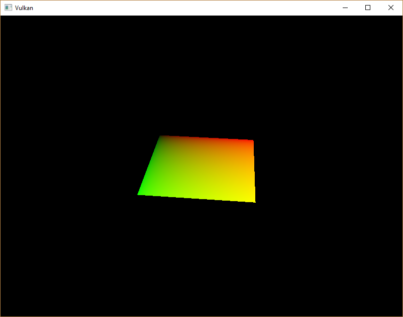
绿色通道代表水平坐标,红色通道代表垂直坐标。黑色和黄色的角点确认了纹理坐标在整个正方形上从 0, 0 正确插值到 1, 1。使用颜色可视化数据是着色器编程中相当于 printf 调试的方法,在没有更好的选择的情况下!
组合的图像采样器描述符在 GLSL 中由一个采样器 uniform 表示。在片段着色器中添加对它的引用
layout(binding = 1) uniform sampler2D texSampler;对于其他类型的图像,存在等效的 sampler1D 和 sampler3D 类型。请确保在此处使用正确的绑定。
void main() {
outColor = texture(texSampler, fragTexCoord);
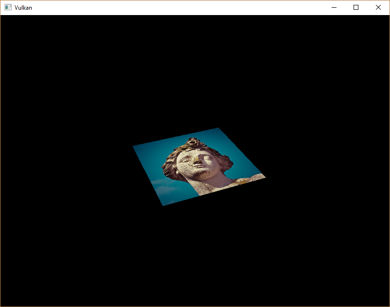
}纹理使用内置的 texture 函数进行采样。它接受一个 sampler 和坐标作为参数。采样器会自动在后台处理过滤和转换。现在,当您运行应用程序时,您应该在正方形上看到纹理了
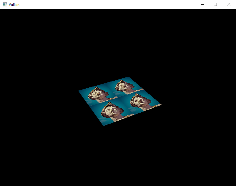
尝试通过将纹理坐标缩放到大于 1 的值来试验寻址模式。例如,以下片段着色器在使用 VK_SAMPLER_ADDRESS_MODE_REPEAT 时会产生下图中的结果
void main() {
    outColor = texture(texSampler, fragTexCoord * 2.0);
}
您还可以使用顶点颜色来操作纹理颜色
void main() {
    outColor = vec4(fragColor * texture(texSampler, fragTexCoord).rgb, 1.0);
}
我在这里分离了 RGB 和 alpha 通道,以避免缩放 alpha 通道。

您现在知道如何在着色器中访问图像了!当与也写入帧缓冲区的图像结合使用时,这是一种非常强大的技术。您可以使用这些图像作为输入来实现很酷的效果,例如后处理和 3D 世界中的相机显示。
在下一章中,我们将学习如何添加深度缓冲来正确排序对象。